Showing posts with label LECTURE. Show all posts
Showing posts with label LECTURE. Show all posts
Saturday, 21 December 2013
Difference between Harvard and Von Neumann computer architectures
There are basically two types of digital computer architectures. The first one is called Von Neumann architecture and later Harvard architecture was adopted for designing digital computers.
Von Neumann Architecture:

- It is named after the mathematician and early computer scientist John Von Neumann.
- Used in conventional processors found in PCs and Servers, and embedded systems with only control functions.
- The computer has single storage system(memory) for storing data as well as program to be executed.
- Processor needs two clock cycles to complete an instruction.Pipelining the instructions is not possible with this architecture.
- In the first clock cycle the processor gets the instruction from memory and decodes it. In the next clock cycle the required data is taken from memory. For each instruction this cycle repeats and hence needs two cycles to complete an instruction.
- The code is executed serially and takes more clock cycles.
- There is no exclusive Multiplier.
- Absence of Barrel Shifte.
- The programs can be optimized in lesser size.

- The name is originated from "Harvard Mark I" a relay based old computer.
- Used in DSPs and other processors found in latest embedded systems and Mobile communication systems, audio, speech, image processing systems.
- The computer has two separate memories for storing data and program.
- Processor can complete an instruction in one cycle if appropriate pipelining strategies are implemented.
- In the first stage of pipeline the instruction to be executed can be taken from program memory.In the second stage of pipeline data is taken from the data memory using the decoded instruction or address.
- The code is executed in parallel.
- It has MAC (Multiply Accumulate).
- Barrel Shifter help in shifting and rotating operations of the data.
-
The program tend to grow big in size.

Tuesday, 8 October 2013
CAPACITOR WORKING AND EXPALANATION
How Capacitor Work?


In general you must have now understood what is a capacitor? But there are still numerous different complicated ways through which a capacitor may be configured. Hopefully you will get to read them in my forth coming articles.
 |
| Various Capacitors |
A capacitor (originally known as condenser) is a passive two-terminal electrical component used to store energy in an electric field. The forms of practical capacitors vary widely, but all contain at least two electrical conductors separated by a dielectric (insulator); for example, one common construction consists of metal foils separated by a thin layer of insulating film. Capacitors are widely used as parts of electrical circuits in many common electrical devices.
How Does a Capacitor role?
 From the symbol of a capacitor we notice that, it has two plates or poles separated by a space. A capacitor is just prepared up that way practically. A capacitor internally consists of two conducting plates separated by an insulator or the dielectric.

Working principle:When a voltage (DC) is applied to its pair of conducting plates, an electricfield is generated across them. This field or energy is stored across the plates in the form of charge. The relation between voltage, charge and the capacitance is expressed through the formula:
C = Q/V.
Where C = Capacitance, Q = Charge and V = Voltage.
So it can be clearly understood from the above formula that the potential drop or the voltage across the plates of a capacitor is proportional to the instantaneous charge Q stored in the capacitor. The unit of measurement of capacitance is Farad. The value of a capacitor (in Farads) depends on the amount of charge it can store in it.
What is the uses of capacitor ?
In electronic circuits, capacitors are usually used for the following purposes:
Filter AC: A power supply circuit may be rendered useless without a filter capacitor. Even after full wave rectification, the voltage of a power supply may be full of ripples. A filter capacitor smooths down these ripples and fills up the voltage” notches” or gaps by discharging its internal stored energy. Thus the circuit connected to it is able to receive a clean DC supply voltage.

To Block DC: A very interesting character of capacitors is to block DC (Direct Current) and allow AC (Alternating Current) to pass through it. The internal operation of many complicated electronic circuits involves the use of frequencies which are in fact small alternating voltages. But since every circuit requires a DC to be useful, sometimes it becomes very essential to block it from entering the restricted areas of the circuit. This is effectively countered using capacitors which allow the frequency part to pass and block the DC.

To Resonate:
As shown in the adjoining diagram, a capacitor when conjugated with an inductor will resonate to a particular frequency which is fixed by their values. In simple words the pair will respond and lock to a particular external applied frequency and will start oscillating at the same frequency itself. The behavior is well exploited in RF circuits, Transmitters, metal detectors etc.
Thursday, 19 September 2013
Difference between step-up transformer and voltage amplifier
A step up transformer basically increases the magnitude of primary applied voltage that is increases the amplitude of voltage wave form. A voltage amplifier does exactly the same.
Than a very strange but thinkable question comes what is the difference between the two and can we use a small step up transformer in place of voltage amplifier and vice-versa?
Than a very strange but thinkable question comes what is the difference between the two and can we use a small step up transformer in place of voltage amplifier and vice-versa?
Differences
| Transformer | Amplifier |
| Transformers are unable to amplify (step up) an ac input Voltage without reducing (stepping down) it`s current capability. | Amplifier can amplify both current and Voltage at the same time. We can have 1V at 1uA to drive the input but might also get many volts at many Amps at the output. |
| Transformer`s coil windings never requires a dc Voltage to operate. Sometimes a dc Voltage might be present in a transformer winding for auxiliaries but the dc is not required for the operation of the transformer. | Amplifier almost always requires a dc working supply Voltage to operate. |
| Transformer has more winding added to its secondary winding to obtain Voltage amplification. | An Amplifier actually modulates a fixed dc source Voltage in response to an ac input Voltage to obtain output Voltage amplification. |
| A transformer`s input current is proportional to its load current. | Amplifier’s input current is normally almost independent of its load current. |
| A transformer is like a gearbox, whereas an amplifier is like an engine. The gearbox converts energy like a transformer. | Amplifier is like an engine, which consumes fuel to give output. Similarly amplifier consumed DC supply to give output. |
| A step up transformer can amplify a specified type of input which is the sinusoidal input or time varying input and add to that the range of input the transformer is very flexible in range. | Amplifier can amplify any signal and while the amplifier would have a limited range then in the saturation state. |
| In an ideal transformer output impedance is equal to the source impedance times the square of the turns ratio. | An amplifier can have output impedance that is independent of the source impedance. |
Friday, 1 March 2013
Electrical Machines : Stepper Motors Working and Principle and Stepper motor Animation
To learn and understand the principle of operation of the stepper motors, to me is very important. A stepper motor is always the simplest, cheapest and lighter solution for accurate positioning systems. It this article, i will explain how the stepper motors are made, and how they work. It is necessary to have some very basic knowledge for the operation of DC motors to follow this article.
What is a stepper motor?
First of all, a stepper motor is a motor. This means, that it converts electrical power into mechanical power. The main difference between them and all the other motors, is the way they revolve. Unlike other motors, stepper motors does not continuously rotate! Instead, they rotate in steps (from which they got the name). Each step is a fraction of a full circle. This fraction depends mostly from the mechanical parts of the motor, and from the driving method. The stepper motors also differs in the way they are powered. Instead of an AC or a DC voltage, they are driven (usually) with pulses. Each pulse is translated into a degree of rotation. For example, an 1.8o stepper motor, will revolve its shaft 1.8o on every pulse that arrives. Often, due to this characteristic, stepper motors are called also digital motors.
A very basic stepper motor
As all motors, the stepper motors consists of a stator an a rotor. The rotor carries a set of permanent magnets, and the stator has the coils. The very basic design of a stepper motor would be as follows:
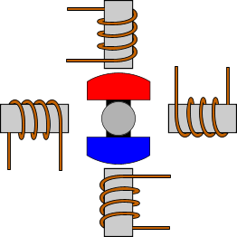
There are 4 coils with 90o angle between each other fixed on the stator. The way that the coils are interconnected, will finally characterize the type of stepper motor connection. In the above drawing, the coils are not connected together. The above motor has 90o rotation step. The coils are activated in a cyclic order, one by one. The rotation direction of the shaft is determined by the order that the coils are activated. The following animation demonstrates this motor in operation. The coils are energized in series, with about 1sec interval. The shaft rotates 90o each time the next coil is activated:
Driving modes
In this section, i will explain the various ways that the coils are energized, and the results on the motors shaft.
Wave drive or Single-Coil Excitation
The first way is the one described previously. This is called Single-Coil Excitation, and means that only one coil is energized each time. This method is rarely used, generally when power saving is necessary. It provides less than half of the nominal torque of the motor, therefore the motor load cannot be high.
This motor will have 4 steps per full cycle, that is the nominal number of steps per cycle.
Full step drive
The second and most often used method, is the Full step drive. According to this method, the coils are energized in pairs. According to the connection of the coils (series or parallel) the motor will require double the voltage or double the current to operate that needs when driving with Single-Coil Excitation. Yet, it produces 100% the nominal torque of the motor.
This motor will have 4 steps per full cycle, that is the nominal number of steps per cycle.
Half stepping
This is a very interesting way to achieve double the accuracy of a positioning system, without changing anything from the hardware! According to this method, all coil pairs can be energized simultaneously, causing the rotor to rotate half the way as a normal step. This method can be single-coil or two-coil excitation as well. The following animations make this clear:
 |  |
| Single-Coil excitation | Two-Coil excitation |
With this method, the same motor will have double the steps per revolutions, thus double the accuracy in positioning systems. For example, this motor will have 8 steps per cycle!
Microstepping
Microstepping is the most common method to control stepper motors nowadays. The idea of microstepping, is to power the coils of the motor NOT with pulses, but with a waveform similar to a sin waveform. This way, the positioning from one step to the other is smoother, making the stepper motor suitable to be used for high accuracy applications such as CNC positioning systems. Also, the stress of the parts connected on the motor, as well as the stress on the motor itself is significantly decreased. With microstepping, a stepper motor can rotate almost continuous, like simple DC motors.
The waveform that the coils are powered with, is similar to an AC waveform. Digital waveforms can also be used. here are some examples:
 |  |  |
| Powering with sine wave | Powering with digital signal | Powering with high resolution digital signal |
The microstepping method is actually a power supply method, rather than coil driving method. Therefore, the microstepping can be applied with single-coil excitation and full step drive. The following animation demonstrated this method:
Although it seems that the microstepping increases the steps even further, usually this does not happen. In high accuracy applications, trapezoidal gears are used to increase the accuracy. This method is used to ensure smooth motion.
Tuesday, 9 October 2012
Methods of Starting of Induction Motor
Direct-on-line starter
 The starter is also called as line-to-line starter. The line starting is usually accomplished by means of a magnetic switch or contactor, which can be controlled by push buttons at convenient points. The "start" push button is normally open and stop button usually closed. When the start push button is pressed it closes a control circuit from the live line L, through the stop button the solenoid M of the magnetic contactor and a temperature over load relay R, to the live line wire L2. The current ion the solenoid, M closes the main contactors and throws full line voltage on the motor. The motor starts running. It also closes the switch S, so that current is maintained in the control circuit through the stop push button, even after the start push button is released. The motor can be controlled from several points by using several push button stations. The start push buttons are connected in parallel and the stop push buttons in series.
The thermal overload relay is set protect the motor against continuous overload. It is not affected by large starting current, or by sudden momentary over loads. Fuses or circuit breakers in the supply line must carry the starting current. When the stop button is pressed; it disconnects the solenoid, M that de-magnetizes. The supply contactors go to the original position disconnecting the motor from the three-phase supply. The motor comes to stop. The start button has to be pressed for re-starting the motor.
Merits of DOL starter
1. Simple in construction
2. Easy to install
3. Easy to maintain
4. Less expenditure for maintenance
Demerits of DOL starter
1. Used only for small horsepower motors.
2. starting current is heavy since started with full voltage.
3. Suitable only for motors which attain to their rated speed in a very short time.
Primary resistor or reactor starter

The purpose is to drop some voltage and hence reduce the voltage applied across the motor terminals. The initial current drawn by the motor is reduced. The current varies directly as the voltage. But the torque varies as the square of the applied voltage. If the voltage applied across the motor terminal is reduced by 50%, starting current is reduced by 50 % but torque is reduced to 25% of the full-voltage value. The figure shows such a circuit, in which either resistance or reactance coils may be used to produce a sufficient reduction in stator voltage at the instant of starting. This method of starting is sometimes called "primary impedance acceleration". Reduced voltage starting by means of series stator resistance will improve the starting power factor, but greater losses are produced. The advantage of reactor starting is reduced losses.
Star delta starter
This method is used in the case of motors which are built to run normally with a delta-connected stator winding.
Induction Motors: Analysis and Torque Control (Power Systems)
By means of a triple- pole- double- throw switch, the winding is connected in star at starting and delta connected when running as shown in figure.
When start connected, the voltage applied per phase is reduced by 3 times. The current taken from the line is 58 percent of that at normal voltage. But the starting torque is reduced to 0.582 or 33% of that at normal voltage. When the motor reaches sufficient speed the switch is thrown over thereby connecting the motor in delta across the line.

It is clear that star-delta switch is equivalent to an auto-transformer of ratio 1/3 or 58% approx. This method is cheap and effectively provides the starting torque required in not more than 1.5 times the full load torque. When the operating handle is put downwards the terminals A1, B1, C1 are shorted. Now the stator windings are connected in star and energized by three-phase supply.

When the motor has picked up the required speed the operating handle is put upwards and the stator windings are connected in delta across the three-phase supply.
The Induction Motor: Its Theory and Design, Set Forth by a Practical Method of Calculation
In star-delta starter also the no-volt release and over load release are provided to protect the motor against the failure of supply and overload. This type of starters is used to start the motors from the range of 7.5 hp to 20 hp squirrel cage induction motors.
Motor Starting - Star Delta Characteristics:
Available starting current: 33%
Peak starting current: 1.3 to 2.6 In
Peak starting torque: 33%
Advantages:
Simple
Low Cost
Good Torque/Current Performance
Disadvantages:
Auto transformer starterLow Starting Torque
Break In Supply - Possible Transients
Six Terminal Motor Required

The figure shows the usual connection made through an auto-transformer to a three-phase motor. By use of control gear mounted on the top of the auto-transformer voltage applied to the motor is varied and finally full voltage is applied across the motor terminals. In the above method of starting there are no tapings in the auto-transformer. But in auto-transformer there are tapings. Only one tapping is used at the time of starting. The figure shows an auto-transformer with protective devices. The starter is also provided with change over switch. As the motor comes to full speed the change over switch is thrown to run position. The changeover switch may be hand operated or automatic through a time delay relay. This figure shows an auto-transformer starter, which is provided with no-volt release and over-load release as protective devices.

Rotor resistance starter
Slip ring induction motors are practically always started with full line voltage applied across the stator terminals.
Induction Motors: Analysis and Torque Control (Power Systems)
The value of starting current can be adjusted by introducing a variable resistance in the rotor circuit through slip rings. The external resistance connected in the rotor circuit is in the form of a rheostat connected in star. The resistance gradually cut out of the rotor circuit as the motor picks up speed and finally the slip rings are short-circuited. By increasing the rotor resistance, the rotor current is reduced at starting since impedance increases. The protective devices, no-volt relay and over-load relay can be provided in this starter also.
 The figure shows a rotor resistance starter with protective devices.
When the on button is pressed the no-volt relay energizes and closes the line contactor. The full voltage is applied to the stator terminals. When the on button is released, the relay gets supply through the contactor. The rotor external resistance is cut step by step. Finally the slip rings are short-circuited. The brushes may be lifted from slip-rings surfaces when the motor runs at normal speed or during normal working conditions. This is to avoid wear and tear and also to reduce the frictional losses.
The value of starting current can be adjusted by introducing a variable resistance in the rotor circuit through slip rings. The external resistance connected in the rotor circuit is in the form of a rheostat connected in star. The resistance gradually cut out of the rotor circuit as the motor picks up speed and finally the slip rings are short-circuited. By increasing the rotor resistance, the rotor current is reduced at starting since impedance increases. The protective devices, no-volt relay and over-load relay can be provided in this starter also.
When the on button is pressed the no-volt relay energizes and closes the line contactor. The full voltage is applied to the stator terminals. When the on button is released, the relay gets supply through the contactor. The rotor external resistance is cut step by step. Finally the slip rings are short-circuited. The brushes may be lifted from slip-rings surfaces when the motor runs at normal speed or during normal working conditions. This is to avoid wear and tear and also to reduce the frictional losses.
Characteristics:
- Available starting current: 70%
- Peak starting current: < 2.5 In
- Peak starting torque:
- Good Starting Current/Torque Performance
- Adjustable Settings
- No Break in Motor Supply During Starting
- Expensive
- Slip Ring Motor Required
- Resistance Bank Required
Wednesday, 12 September 2012
Reluctance Motor Working and Construction
UNIT II - Electric Machines and Drives
The variable reluctance motor is based on the principle that an unrestrained piece of iron will move to complete a magnetic flux path with minimum reluctance, the magnetic analog of electrical resistance.
Animation

Fig. 7.1 Reluctance motor
WORKING PRINCIPLE
If an iron piece is placed in a magnetic field, it aligns itself in a minimum reluctance position and gets locked magnetically.
MATHEMATICAL ANALYSIS
Consider an elementary reluctance motor as shown in the Fig. 7.2


 Substituting the values of i and L,


The torque-speed characteristic is shown in the Fig. 7.3 The starting torque is highly dependent on the position of the rotor.
 Fig. 7.3 Torque-speed characteristics of reluctance motor
ADVANTAGES
LIMITATIONS
APPLICATIONS
If slots are cut into the conductorless rotor of an induction motor, corresponding to the stator slots, a synchronous reluctance motor results. It starts like an induction motor but runs with a small amount of synchronous torque. The synchronous torque is due to changes in reluctance of the magnetic path from the stator through the rotor as the slots align. This motor is an inexpensive means of developing a moderate synchronous torque. Low power factor, low pull-out torque, and low efficiency are characteristics of the direct power line driven variable reluctance motor. Such was the status of the variable reluctance motor for a century before the development of semiconductor power control.
 Reluctance is a function of rotor position in a variable reluctance motor.
Sequential switching (Figure below) of the stator phases moves the rotor from one position to the next. The mangetic flux seeks the path of least reluctance, the magnetic analog of electric resistance. This is an over simplified rotor and waveforms to illustrate operation.

The variable reluctance motor is based on the principle that an unrestrained piece of iron will move to complete a magnetic flux path with minimum reluctance, the magnetic analog of electrical resistance.
Animation
A four-phase 8/6 switched-reluctance motor is shown in cross section. In order to produce continuous shaft rotation, each of the four stator phases is energized and then de-energized in succession at specific positions of the rotor as illustrated.
- The reluctance motor has basically two main parts called stator and rotor.
- The stator has a laminated construction, made up of stampings.
- The stampings are slotted on its periphery to carry the winding called stator winding. The stator carries only one winding.
- This is excited by single phase a.c. supply. The laminated construction keeps iron losses to minimum.
- The stampings are made up of material like silicon steel which minimises the hysteresis loss.
- The stator winding is wound for certain definite number of poles.
- The rotor has a particular shape. Due to its shape, the air gap between stator and rotor is not uniform. No d.c. supply is given to the rotor.
- The rotor is free to rotate. The reluctance i.e. resistance of magnetic circuit depends on the air gap.
- More the air gap, more is the reluctance and viceversa. Due to variable air gap between stator and rotor, when rotor rotates, reluctance between stator and rotor also changes.
- The stator and rotor are designed in such a manner that the variation of the inductance of the windings is sinusoidal with respect to the rotor position.
- The construction of the reluctance motor is shown in the Fig. 7.1(a) while the practical rotor of a reluctance motor is shown in the Fig. 7.1(b)
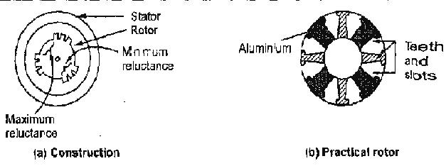
Fig. 7.1 Reluctance motor
WORKING PRINCIPLE
- The stator consists of a single winding called main winding. But single winding can not produce rotating magnetic field. So for production of rotating magnetic field, there must be at least two windings separated by certain phase angle.
- Hence stator consists of an additional winding called auxiliary winding which consists of capacitor in series with it.
- Thus there exists a phase difference between the currents carried by the two windings and corresponding fluxes.
- Such two fluxes react to produce the rotating magnetic field. The technique is called split phase technique of production of rotating magnetic field.
- The speed of this field is synchronous speed which is decided by the number of poles for which stator winding is wound.
If an iron piece is placed in a magnetic field, it aligns itself in a minimum reluctance position and gets locked magnetically.
- Similarly in the reluctance motor, rotor tries to align itself with the axis of rotating magnetic field in a minimum reluctance position.
- But due to rotor inertia it is not possible when rotor is standstill. So rotor starts rotating near synchronous speed as a squirrel cage induction motor.
- When the rotor speed is about synchronous, stator magnetic field pulls rotor into synchronism i.e. minimum reluctance position and keeps it magnetically locked.
- Then rotor continues to rotate with a speed equal to synchronous speed. Such a torque exerted on the rotor is called the reluctance torque.
- Thus finally the reluctance motor runs as a synchronous motor. The resistance of the rotor must be very small and the combined inertia of the rotor and the load should be small to run the motor as a synchronous motor
MATHEMATICAL ANALYSIS
Consider an elementary reluctance motor as shown in the Fig. 7.2

- The variation of the inductance of the windings is sinusoidal with respect to rotor position.
- The variation of the inductance with respect toO is of double frequency and is given by,

- The stator winding is exciteal by a.c. supply hence
- The energy stored is a function of inductance and given by,

- The flux linkage is given by,

- Then the torque is given by


- If rotor is rotating at an angular velocity corn then finally the torque equation can be expressed interms of ω and ωm as,

- The above equation gives instantaneous torque produced. The average torque is zero as average of each term in the above equation is zero.
- The value of torque is not zero when ω = ωm and at this condition the magnitude of the average torque is,

- The speed corresponding to the frequency ω = ωm is nothing but the synchronous speed. The is a torque angle. The maximum torque occurs at δ = 45º which is termed as pull-out torque.of synchronism.
The torque-speed characteristic is shown in the Fig. 7.3 The starting torque is highly dependent on the position of the rotor.

ADVANTAGES
- The reluctance motor has following advantages,
- No d.c. supply is necessary for rotor.
- Constant speed characteristics.
- Robust construction.
- Less maintenance.
LIMITATIONS
- The reluctance motor has following limitations,
- Less efficiency
- Poor power factor
- Need of very low inertia rotor.
- Less capacity to drive the loads.
APPLICATIONS
- This motor is used in signaling devices, control apparatus, automatic regulators, recording instruments, clocks and all kinds of timing devices, teleprinters, gramophones etc.
Synchronous reluctance
If the rotating field of a large synchronous motor with salient poles is de-energized, it will still develop 10 or 15% of synchronous torque. This is due to variable reluctance throughout a rotor revolution. There is no practical application for a large synchronous reluctance motor. However, it is practical in small sizes.If slots are cut into the conductorless rotor of an induction motor, corresponding to the stator slots, a synchronous reluctance motor results. It starts like an induction motor but runs with a small amount of synchronous torque. The synchronous torque is due to changes in reluctance of the magnetic path from the stator through the rotor as the slots align. This motor is an inexpensive means of developing a moderate synchronous torque. Low power factor, low pull-out torque, and low efficiency are characteristics of the direct power line driven variable reluctance motor. Such was the status of the variable reluctance motor for a century before the development of semiconductor power control.
Switched reluctance
If an iron rotor with poles, but without any conductors, is fitted to a multi-phase stator, a switched reluctance motor, capable of synchronizing with the stator field results. When a stator coil pole pair is energized, the rotor will move to the lowest magnetic reluctance path. (Figure below) A switched reluctance motor is also known as a variable reluctance motor. The reluctance of the rotor to stator flux path varies with the position of the rotor.
Sequential switching (Figure below) of the stator phases moves the rotor from one position to the next. The mangetic flux seeks the path of least reluctance, the magnetic analog of electric resistance. This is an over simplified rotor and waveforms to illustrate operation.
Advantages
- Simple construction- no brushes, commutator, or permanent magnets, no Cu or Al in the rotor.
- High efficiency and reliability compared to conventional AC or DC motors.
- High starting torque.
- Cost effective compared to bushless DC motor in high volumes.
- Adaptable to very high ambient temperature.
- Low cost accurate speed control possible if volume is high enough.
- Current versus torque is highly nonlinear
- Phase switching must be precise to minimize ripple torque
- Phase current must be controlled to minimize ripple torque
- Acoustic and electrical noise
- Not applicable to low volumes due to complex control issues
Wednesday, 22 August 2012
Electrical Machines Basics
An Electrical machine is a device that converts mechanical energy to electrical energy or vice versa, and changes AC voltage from one level to another level.
Electrical machines are divided into three parts:
GENERATOR
A generator is the device that converts mechanical energy at its prime mover to produce constant electrical energy at its output. In more technical words, it is a dynamic electrical energy machine. Generator is classified into two types: AC generator and DC generator.
The basic requirements for a dynamically induced emf to exist are the following: (1) A steady magnetic field (2) A conductor capable of carrying current (3) The conductor to move in the magnetic field.
AC generator is the generator that converts mechanical energy at its prime mover into AC electricity.
AC generator is classified into several types:
Asynchronous AC generator or induction AC generator, an AC generator whose field current is supplied by magnetic induction into the field windings.
Synchronous AC generator, an AC generator whose magnetic field current is provided by a separate DC current source, either external DC source or mounted DC source.
DC generator is the generator that produces DC power i.e., constant power P=V*I by taking mechanical energy as input. Example of a DC generator is dynamo.
Motor is the device that converts electrical energy at its input to produce mechanical energy. Motor is classified into two types: AC motor and DC motor.
DC motor is the motor that converts DC electricity into mechanical energy. Its main components are stator, rotor, windings (field windings and armature windings) and commutator
Transformer
Transformer is the device that converts AC voltage from one level to another level higher or lower, or even to the same level without changing the frequency. It works based on the principle of mutual induction, so its power remains approximately constant, where as frequency also remains the same.
Electrical Engineering Basics
Electrical engineering is a field of engineering that generally deals with the study and application of electricity, electronics and electromagnetism. The field first became an identifiable occupation in the late nineteenth century after commercialization of the electric telegraph and electrical power supply. It now covers a range of subtopics including power, electronics, control systems, signal processing and telecommunications.
POWER SYSTEM
Power engineering, also called power systems engineering, is a subfield of engineering that deals with the generation, transmission and distribution of electric power as well as the electrical devices connected to such systems including generators, motors and transformers. Although much of the field is concerned with the problems of three-phase AC power - the standard for large-scale power transmission and distribution across the modern world - a significant fraction of the field is concerned with the conversion between AC and DC power as well as the development of specialized power systems such as those used in aircraft or for electric railway networks.
BASICS OF ELECTRIC POWER
Electric power is the mathematical product of two quantities: current and voltage. These two quantities can vary with respect to time (AC power) or can be kept at constant levels (DC power).
Most refrigerators, air conditioners, pumps and industrial machinery use AC power whereas most computers and digital equipment use DC power (the digital devices you plug into the mains typically have an internal or external power adapter to convert from AC to DC power). AC power has the advantage of being easy to transform between voltages and is able to be generated and utilized by brushless machinery. DC power remains the only practical choice in digital systems and can be more economical to transmit over long distances at very high voltages.
The ability to easily transform the voltage of AC power is important for two reasons: Firstly, power can be transmitted over long distances with less loss at higher voltages. So in power networks where generation is distant from the load, it is desirable to step-up the voltage of power at the generation point and then step-down the voltage near the load. Secondly, it is often more economical to install turbines that produce higher voltages than would be used by most appliances, so the ability to easily transform voltages means this mismatch between voltages can be easily managed.
Solid state devices, which are products of the semiconductor revolution, make it possible to transform DC power to different voltages, build brushless DC machines and convert between AC and DC power. Nevertheless, devices utilizing solid state technology are often more expensive than their traditional counterparts, so AC power remains in widespread use.
POWER
Power Engineering deals with the generation, transmission and distribution of electricity as well as the design of a range of related devices. These include transformers, electric generators, electric motors and power electronics.
The power grid is an electrical network that connects a variety of electric generators to the users of electric power. Users purchase electricity from the grid avoiding the costly exercise of having to generate their own. Power engineers may work on the design and maintenance of the power grid as well as the power systems that connect to it. Such systems are called on-grid power systems and may supply the grid with additional power, draw power from the grid or do both.
Power engineers may also work on systems that do not connect to the grid. These systems are called off-grid power systems and may be used in preference to on-grid systems for a variety of reasons. For example, in remote locations it may be cheaper for a mine to generate its own power rather than pay for connection to the grid and in most mobile applications connection to the grid is simply not practical.
Today, most grids adopt three-phase electric power with alternating current. This choice can be partly attributed to the ease with which this type of power can be generated, transformed and used. Often, the power is split before it reaches residential customers whose low-power appliances rely upon single-phase electric power. However, many larger industries and organizations still prefer to receive the three-phase power directly because it can be used to drive highly efficient electric motors such as three-phase induction motors.
Transformers play an important role in power transmission because they allow power to be converted to and from higher voltages. This is important because higher voltages suffer less power loss during transmission. This is because higher voltages allow for lower current to deliver the same amount of power, as power is the product of the two. Thus, as the voltage steps up, the current steps down. It is the current flowing through the components that result in both the losses and the subsequent heating. These losses, appearing in the form of heat, are equal to the current squared times the electrical resistance through which the current flows, so as the voltage goes up the losses are dramatically reduced.
For these reasons, electrical substations exist throughout power grids to convert power to higher voltages before transmission and to lower voltages suitable for appliances after transmission.
Components
Power engineering is a network of interconnected components which convert different forms of energy to electrical energy. Modern power engineering consists of three main subsystems: the generation subsystem, the transmission subsystem, and the distribution subsystem. In the generation subsystem, the power plant produces the electricity. The transmission subsystem transmits the electricity to the load centers. The distribution subsystem continues to transmit the power to the customers.
Generation
Generation of electrical power is a process whereby energy is transformed into an electrical form. There are several different transformation processes, among which are chemical, photo-voltaic, and electromechanical. Electromechanical energy conversion is used in converting energy from coal, petroleum, natural gas, uranium, water flow, and wind into electrical energy. Of these, all except the wind energy conversion process take advantage of the synchronous AC generator coupled to a steam, gas or hydro turbine such that the turbine converts steam, gas, or water flow into rotational energy, and the synchronous generator then converts the rotational energy of the turbine into electrical energy. It is the turbine-generator conversion process that is by far most economical and consequently most common in the industry today.
The AC synchronous machine is the most common technology for generating electrical energy. It is called synchronous because the composite magnetic field produced by the three stator windings rotate at the same speed as the magnetic field produced by the field winding on the rotor. A simplified circuit model is used to analyze steady-state operating conditions for a synchronous machine. The phasor diagram is an effective tool for visualizing the relationships between internal voltage, armature current, and terminal voltage. The excitation control system is used on synchronous machines to regulate terminal voltage, and the turbine-governor system is used to regulate the speed of the machine.
The operating costs of generating electrical energy is determined by the fuel cost and the efficiency of the power station. The efficiency depends on generation level and can be obtained from the heat rate curve. We may also obtain the incremental cost curve from the heat rate curve. Economic dispatch is the process of allocating the required load demand between the available generation units such that the cost of operation is minimized.
Transmission
The electricity is transported to load locations from a power station to a transmission subsystem. Therefore we may think of the transmission system as providing the medium of transportation for electric energy. The transmission system may be subdivided into the bulk transmission system and the sub-transmission system. The functions of the bulk transmission are to interconnect generators, to interconnect various areas of the network, and to transfer electrical energy from the generators to the major load centers. This portion of the system is called "bulk" because it delivers energy only to so-called bulk loads such as the distribution system of a town, city, or large industrial plant. The function of the sub-transmission system is to interconnect the bulk power system with the distribution system.
Transmission circuits may be built either underground or overhead. Underground cables are used predominantly in urban areas where acquisition of overhead rights of way are costly or not possible. They are also used for transmission under rivers, lakes and bays. Overhead transmission is used otherwise because, for a given voltage level, overhead conductors are much less expensive than underground cables.
The transmission system is a highly integrated system. It is referred to the substation equipment and transmission lines. The substation equipment contain the transformers, relays, and circuit breakers. Transformers are important static devices which transfer electrical energy from one circuit with another in the transmission subsystem. Transformers are used to step up the voltage on the transmission line to reduce the power loss which is dissipated on the way. A relay is functionally a level-detector; they perform a switching action when the input voltage (or current) meets or exceeds a specific and adjustable value. A circuit breaker is an automatically-operated electrical switch designed to protect an electrical circuit from damage caused by overload or short circuit. A change in the status of any one component can significantly affect the operation of the entire system. There are three possible causes for power flow limitations to a transmission line. These causes are thermal overload, voltage instability, and rotor angle instability. Thermal overload is caused by excessive current flow in a circuit causing overheating. Voltage instability is said to occur when the power required to maintain voltages at or above acceptable levels exceeds the available power. Rotor angle instability is a dynamic problem that may occur following faults, such as short circuit, in the transmission system. It may also occur tens of seconds after a fault due to poorly damped or undamped oscillatory response of the rotor motion.
Distribution
The distribution system transports the power from the transmission system to the customer. The distribution systems are typically radial because networked systems are more expensive. The equipment associated with the distribution system includes the substation transformers connected to the transmission systems, the distribution lines from the transformers to the customers and the protection and control equipment between the transformer and the customer. The protection equipment includes lightning protectors, circuit breakers, disconnectors and fuses. The control equipment includes voltage regulators, capacitors, relays and demand side management equipment.
Subscribe to:
Posts (Atom)