Friday, 13 September 2013
Electrical and Electronics Engineering Anna University BE/BTech Fourth Semester Question Paper

Electrical and Electronics Engineering Fourth Semester Question Paper
Subject 1. MA 2264 - Numerical Methods Anna University Question Paper
- Nov/Dec 2011 QP
- April/May 2011 QP
- Nov/Dec 2010 QP
- April/May 2010 QP
Subject 2. EE 2251 Electrical Machines – 1 Anna University Question Paper
Subject 3. EE 2252 Power Plant Engineering Anna University Question Paper
Subject 5. EE 2254 Linear Intergraded Circuits and Applications Anna University Question Paper
Subject 6. EE 2255 Digital Logic Circuits Anna University Question Paper
Anna University Question Paper, Anna University BE/BTECH Question Paper, Anna University BE/BTECH Electrical and Electronics Question Paper, Anna University BE/BTECH Electrical and Electronics Previous Year Question Paper, Anna University BE/BTECH Electrical and Electronics Previous Year Old Question Paper, Anna University BE/BTECH Electrical and Electronics Previous Year Old Semester Question Paper, Anna University EEE Question Paper.

Wednesday, 4 September 2013
Digital logic and computer design M. Morris Mano

BIBLOGRAPHY:
NAME OF THE BOOK : Digital logic and computer designAUTHOR : M. Morris Mano
PUBLISHER : Prentice-Hall, 1979
ABOUT THIS BOOK:
Topics
- Binary Numbers.
- Octal and Hexadecimal Numbers.
- Complements.
- Binary Logic.
- Boolean Algebra and Logic Gates.
- NAND and NOR Implementation.
- Four-Variable Map.
- Five-Variable Map.
- Ripple Counters.
- RTL and DTL Circuits.
- Transistor-Transistor Logic.
- Digital Integrated Circuits.
- Registers, Counters and the Memory unit.
Thursday, 15 August 2013
Mechanical - Seventh Semester Anna University, Chennai Question Paper - Regulation-2008
Anna University, Chennai Mechanical - Seventh Semester Question Paper - Regulation-2008
Anna University mechanical fifth semseter previous year Question Paper, Anna University BE/BTECH mechanical year Question Paper, Anna University BE/BTECH mechanical Question Paper, Anna University BE/BTECH mechanical Previous Year Question Paper, Anna University BE/BTECH Electrical and Electronics Previous Year Old Question Paper, Anna University BE/BTECH Electrical and Electronics Previous Year Old Semester Question Paper, Anna University mechanical Question Paper, May/June 2012 Anna University Question Paper, Nov/Dec 2011 Anna University Question Paper, April/May 2011 Anna University Question Paper, Nov/Dec 2010 Anna University Question Paper, April/May 2010 Anna University Question Paper.
Subject 1. GE 2022 - Total Quality Management Anna University Question Paper
- May/June 2012 QP
- May/June 2011 QP
- Nov/Dec 2011 QP
- April/May 2009 QP
Subject 2. ME 2401 - Mechatronics Anna University Question Paper
- Nov/Dec 2012 QP
- Nov/Dec 2011 QP
- April/May 2011 QP
Subject 3. ME 2402 Computer Integrated Manufacturing Anna University Question Paper
- May/June 2012 QP
- Nov/Dec 2011 QP
- Nov/Dec 2010 QP
- April/May 2010 QP
Subject 4. ME 2403 Power Plant Engineering Anna University Question Paper
- Nov/Dec 2012 QP
- April/May 2011 QP
- Nov/Dec 2010 QP
- April/May 2010 QP
Subject 5. EE 2027 Process Planning & Cost Estimation Anna University Question Paper
- Nov/Dec 2011 QP
- April/May 2011 QP
- Nov/Dec 2010 QP
- April/May 2010 QP
Subject 6. ME 2029 Design of Jigs, Fixtures & Press Tools Anna University Question Paper
- Nov/Dec 2011 QP
- April/May 2011 QP
- Nov/Dec 2010 QP
- April/May 2010 QP
Subject 7. ME 2030 Composite MaterialsAnna University Question Paper
- Nov/Dec 2012 QP
- April/May 2011 QP
- Nov/Dec 2010 QP
- April/May 2010 QP
Subject 8. EE 2028 Robotics Anna University Question Paper
- Nov/Dec 2011 QP
- April/May 2011 QP
- Nov/Dec 2010 QP
- April/May 2010 QP
Subject 9. ME 2031 Thermal Turbo machines Anna University Question Paper
- Nov/Dec 2011 QP
- April/May 2011 QP
- Nov/Dec 2010 QP
- April/May 2010 QP
Subject 10. ME 2032 Computational Fluid Dynamics Anna University Question Paper
- Nov/Dec 2012 QP
- April/May 2011 QP
- Nov/Dec 2010 QP
- April/May 2010 QP
Subject 12. ME 2038 Thermal Turbo machines Anna University Question Paper
- Nov/Dec 2011 QP
- April/May 2011 QP
- Nov/Dec 2010 QP
- April/May 2010 QP
Anna University Question Paper, Anna University BE/BTECH Question Paper, Anna University BE/BTECH Electrical and Electronics Question Paper, Anna University BE/BTECH Electrical and Electronics Previous Year Question Paper, Anna University BE/BTECH Electrical and Electronics Previous Year Old Question Paper, Anna University BE/BTECH Electrical and Electronics Previous Year Old Semester Question Paper, Anna University EEE Question Paper, May/June 2012 Anna University Question Paper, Nov/Dec 2011 Anna University Question Paper, April/May 2011 Anna University Question Paper, Nov/Dec 2010 Anna University Question Paper, April/May 2010 Anna University Question Paper.
Friday, 1 March 2013
Electrical Machines : Stepper Motors Working and Principle and Stepper motor Animation
To learn and understand the principle of operation of the stepper motors, to me is very important. A stepper motor is always the simplest, cheapest and lighter solution for accurate positioning systems. It this article, i will explain how the stepper motors are made, and how they work. It is necessary to have some very basic knowledge for the operation of DC motors to follow this article.
What is a stepper motor?
First of all, a stepper motor is a motor. This means, that it converts electrical power into mechanical power. The main difference between them and all the other motors, is the way they revolve. Unlike other motors, stepper motors does not continuously rotate! Instead, they rotate in steps (from which they got the name). Each step is a fraction of a full circle. This fraction depends mostly from the mechanical parts of the motor, and from the driving method. The stepper motors also differs in the way they are powered. Instead of an AC or a DC voltage, they are driven (usually) with pulses. Each pulse is translated into a degree of rotation. For example, an 1.8o stepper motor, will revolve its shaft 1.8o on every pulse that arrives. Often, due to this characteristic, stepper motors are called also digital motors.
A very basic stepper motor
As all motors, the stepper motors consists of a stator an a rotor. The rotor carries a set of permanent magnets, and the stator has the coils. The very basic design of a stepper motor would be as follows:
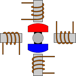
There are 4 coils with 90o angle between each other fixed on the stator. The way that the coils are interconnected, will finally characterize the type of stepper motor connection. In the above drawing, the coils are not connected together. The above motor has 90o rotation step. The coils are activated in a cyclic order, one by one. The rotation direction of the shaft is determined by the order that the coils are activated. The following animation demonstrates this motor in operation. The coils are energized in series, with about 1sec interval. The shaft rotates 90o each time the next coil is activated:
Driving modes
In this section, i will explain the various ways that the coils are energized, and the results on the motors shaft.
Wave drive or Single-Coil Excitation
The first way is the one described previously. This is called Single-Coil Excitation, and means that only one coil is energized each time. This method is rarely used, generally when power saving is necessary. It provides less than half of the nominal torque of the motor, therefore the motor load cannot be high.
This motor will have 4 steps per full cycle, that is the nominal number of steps per cycle.
Full step drive
The second and most often used method, is the Full step drive. According to this method, the coils are energized in pairs. According to the connection of the coils (series or parallel) the motor will require double the voltage or double the current to operate that needs when driving with Single-Coil Excitation. Yet, it produces 100% the nominal torque of the motor.
This motor will have 4 steps per full cycle, that is the nominal number of steps per cycle.
Half stepping
This is a very interesting way to achieve double the accuracy of a positioning system, without changing anything from the hardware! According to this method, all coil pairs can be energized simultaneously, causing the rotor to rotate half the way as a normal step. This method can be single-coil or two-coil excitation as well. The following animations make this clear:
 |  |
| Single-Coil excitation | Two-Coil excitation |
With this method, the same motor will have double the steps per revolutions, thus double the accuracy in positioning systems. For example, this motor will have 8 steps per cycle!
Microstepping
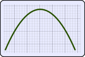
Microstepping is the most common method to control stepper motors nowadays. The idea of microstepping, is to power the coils of the motor NOT with pulses, but with a waveform similar to a sin waveform. This way, the positioning from one step to the other is smoother, making the stepper motor suitable to be used for high accuracy applications such as CNC positioning systems. Also, the stress of the parts connected on the motor, as well as the stress on the motor itself is significantly decreased. With microstepping, a stepper motor can rotate almost continuous, like simple DC motors.
The waveform that the coils are powered with, is similar to an AC waveform. Digital waveforms can also be used. here are some examples:
 | 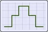 | 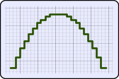 |
| Powering with sine wave | Powering with digital signal | Powering with high resolution digital signal |
The microstepping method is actually a power supply method, rather than coil driving method. Therefore, the microstepping can be applied with single-coil excitation and full step drive. The following animation demonstrated this method:
Although it seems that the microstepping increases the steps even further, usually this does not happen. In high accuracy applications, trapezoidal gears are used to increase the accuracy. This method is used to ensure smooth motion.
Tuesday, 9 October 2012
Methods of Starting of Induction Motor
Direct-on-line starter
 The starter is also called as line-to-line starter. The line starting is usually accomplished by means of a magnetic switch or contactor, which can be controlled by push buttons at convenient points. The "start" push button is normally open and stop button usually closed. When the start push button is pressed it closes a control circuit from the live line L, through the stop button the solenoid M of the magnetic contactor and a temperature over load relay R, to the live line wire L2. The current ion the solenoid, M closes the main contactors and throws full line voltage on the motor. The motor starts running. It also closes the switch S, so that current is maintained in the control circuit through the stop push button, even after the start push button is released. The motor can be controlled from several points by using several push button stations. The start push buttons are connected in parallel and the stop push buttons in series.
The thermal overload relay is set protect the motor against continuous overload. It is not affected by large starting current, or by sudden momentary over loads. Fuses or circuit breakers in the supply line must carry the starting current. When the stop button is pressed; it disconnects the solenoid, M that de-magnetizes. The supply contactors go to the original position disconnecting the motor from the three-phase supply. The motor comes to stop. The start button has to be pressed for re-starting the motor.
Merits of DOL starter
1. Simple in construction
2. Easy to install
3. Easy to maintain
4. Less expenditure for maintenance
Demerits of DOL starter
1. Used only for small horsepower motors.
2. starting current is heavy since started with full voltage.
3. Suitable only for motors which attain to their rated speed in a very short time.
Primary resistor or reactor starter

The purpose is to drop some voltage and hence reduce the voltage applied across the motor terminals. The initial current drawn by the motor is reduced. The current varies directly as the voltage. But the torque varies as the square of the applied voltage. If the voltage applied across the motor terminal is reduced by 50%, starting current is reduced by 50 % but torque is reduced to 25% of the full-voltage value. The figure shows such a circuit, in which either resistance or reactance coils may be used to produce a sufficient reduction in stator voltage at the instant of starting. This method of starting is sometimes called "primary impedance acceleration". Reduced voltage starting by means of series stator resistance will improve the starting power factor, but greater losses are produced. The advantage of reactor starting is reduced losses.
Star delta starter
This method is used in the case of motors which are built to run normally with a delta-connected stator winding.
Induction Motors: Analysis and Torque Control (Power Systems)
By means of a triple- pole- double- throw switch, the winding is connected in star at starting and delta connected when running as shown in figure.
When start connected, the voltage applied per phase is reduced by 3 times. The current taken from the line is 58 percent of that at normal voltage. But the starting torque is reduced to 0.582 or 33% of that at normal voltage. When the motor reaches sufficient speed the switch is thrown over thereby connecting the motor in delta across the line.

It is clear that star-delta switch is equivalent to an auto-transformer of ratio 1/3 or 58% approx. This method is cheap and effectively provides the starting torque required in not more than 1.5 times the full load torque. When the operating handle is put downwards the terminals A1, B1, C1 are shorted. Now the stator windings are connected in star and energized by three-phase supply.

When the motor has picked up the required speed the operating handle is put upwards and the stator windings are connected in delta across the three-phase supply.
The Induction Motor: Its Theory and Design, Set Forth by a Practical Method of Calculation
In star-delta starter also the no-volt release and over load release are provided to protect the motor against the failure of supply and overload. This type of starters is used to start the motors from the range of 7.5 hp to 20 hp squirrel cage induction motors.
Motor Starting - Star Delta Characteristics:
Available starting current: 33%
Peak starting current: 1.3 to 2.6 In
Peak starting torque: 33%
Advantages:
Simple
Low Cost
Good Torque/Current Performance
Disadvantages:
Auto transformer starterLow Starting Torque
Break In Supply - Possible Transients
Six Terminal Motor Required

The figure shows the usual connection made through an auto-transformer to a three-phase motor. By use of control gear mounted on the top of the auto-transformer voltage applied to the motor is varied and finally full voltage is applied across the motor terminals. In the above method of starting there are no tapings in the auto-transformer. But in auto-transformer there are tapings. Only one tapping is used at the time of starting. The figure shows an auto-transformer with protective devices. The starter is also provided with change over switch. As the motor comes to full speed the change over switch is thrown to run position. The changeover switch may be hand operated or automatic through a time delay relay. This figure shows an auto-transformer starter, which is provided with no-volt release and over-load release as protective devices.

Rotor resistance starter
Slip ring induction motors are practically always started with full line voltage applied across the stator terminals.
Induction Motors: Analysis and Torque Control (Power Systems)
The value of starting current can be adjusted by introducing a variable resistance in the rotor circuit through slip rings. The external resistance connected in the rotor circuit is in the form of a rheostat connected in star. The resistance gradually cut out of the rotor circuit as the motor picks up speed and finally the slip rings are short-circuited. By increasing the rotor resistance, the rotor current is reduced at starting since impedance increases. The protective devices, no-volt relay and over-load relay can be provided in this starter also.
 The figure shows a rotor resistance starter with protective devices.
When the on button is pressed the no-volt relay energizes and closes the line contactor. The full voltage is applied to the stator terminals. When the on button is released, the relay gets supply through the contactor. The rotor external resistance is cut step by step. Finally the slip rings are short-circuited. The brushes may be lifted from slip-rings surfaces when the motor runs at normal speed or during normal working conditions. This is to avoid wear and tear and also to reduce the frictional losses.
The value of starting current can be adjusted by introducing a variable resistance in the rotor circuit through slip rings. The external resistance connected in the rotor circuit is in the form of a rheostat connected in star. The resistance gradually cut out of the rotor circuit as the motor picks up speed and finally the slip rings are short-circuited. By increasing the rotor resistance, the rotor current is reduced at starting since impedance increases. The protective devices, no-volt relay and over-load relay can be provided in this starter also.
When the on button is pressed the no-volt relay energizes and closes the line contactor. The full voltage is applied to the stator terminals. When the on button is released, the relay gets supply through the contactor. The rotor external resistance is cut step by step. Finally the slip rings are short-circuited. The brushes may be lifted from slip-rings surfaces when the motor runs at normal speed or during normal working conditions. This is to avoid wear and tear and also to reduce the frictional losses.
Characteristics:
- Available starting current: 70%
- Peak starting current: < 2.5 In
- Peak starting torque:
- Good Starting Current/Torque Performance
- Adjustable Settings
- No Break in Motor Supply During Starting
- Expensive
- Slip Ring Motor Required
- Resistance Bank Required
Subscribe to:
Posts (Atom)